§ 4.5mm Gamebit screwdriver (see photo)
The Nintendo GameCube®, in a way vaguely comparable to the DS/Lite and to a lesser extent to the Wii, uses a hardware- (well, drive firmware's-)based protection against unlicensed/pirate discs; all other protections (ie, region lock), are 100% software and therefore bypassable if the system software (which completely stops running once a disc is booted) can be bypassed.
So once we get an original (or "original") disc running, it can run any arbitrary code freely (this principle is used in game exploits and commercial boot discs - like the famous SD Media Launcher), with running burnt discs as the only exception (and even then, interesting debug commands were later discovered…)
So, why not just use a softmod? It's fully doable, but having to repeat it (which takes the better part of a minute or worse) after every reboot gets boring quickly - and in the case of the SD Media Launcher, SDHC/SDXC are not supported, likely adding a further swap step to the mess!
So, why not just use an ODE (a piece of hardware which provides an SD or USB based "virtual drive")? They certainly have better performance and compatibility, but they don't support audio streaming (used by certain games for background music) and, most importantly, they are hard to find and fit (if you're a DIY person) or hard to afford (in part because of the previous reason) if you want a turnkey solution… New generation models solving these issues are in the works - but of course nothing commercially available…
So, why not just use an IPL ("bootrom") replacement chip? It would certainly be better and more reliable… if only you could still buy them!
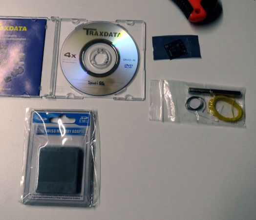
Note: Items marked with "§" are generally available for purchase in convenient bundles (see picture). "Materials" are (without nitpicking) items you have to buy for every single console, "tools" are things you only have to buy once (outside of failures, theft, loss, fire, Chinesium, …).
A GameCube (DOL-001, with serial port 2) and its standard accessories (power brick, your favorite video cable, controller, "optionally" a memory card).
(I said specifically "(DOL-001, with serial port 2)" because I only own and know about this first-generation unit; the basic concept is valid for all models (further caveats apply to the Panasonic Q), but it appears some optical drive boards were redesigned to break wire-less chips such as this one.)
§ an SD Gecko (adapter to connect an SD to a memory card slot)
It's actually an official Nintendo accessory (the DOL-019) that's obviously now impossible to find, but clones are widely available (and maybe still in industrial production) for example from team WiiKey (aka "Wü" or "WiSD"), as are Datel's (though they are considered of low build quality), and you can even make your own using a junk memory card and an SD slot left over from some other project of yours!
Remember, it's a completely passive adapter, therefore (unless it's broken) it has no influence on compatibility/performance (including whether SDHC/XC are supported), and doesn't make the SD a substitute for a memory card (all of these things are up to the individual software running)
§ 4.5mm Gamebit screwdriver (see photo)
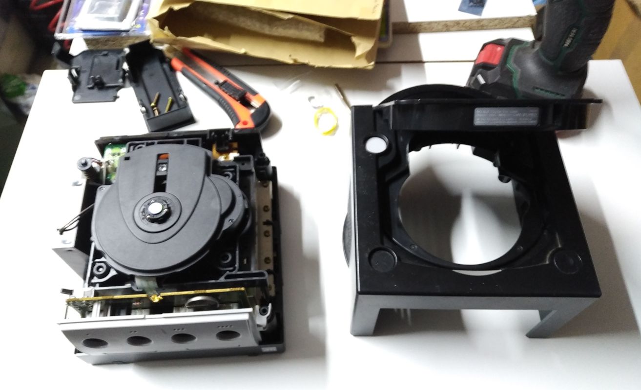
After removing the Game Boy Player or other invasive accessories and all cables, use the Gamebit screwdriver to remove the 4 screws in the large holes under the console.
I do not recommend beginners to use a drill - it's relatively easy to cause damage (cosmetic, if not worse) should it slip….
Then, after returning the console to its normal horizontal position, the top cover lifts straight off.
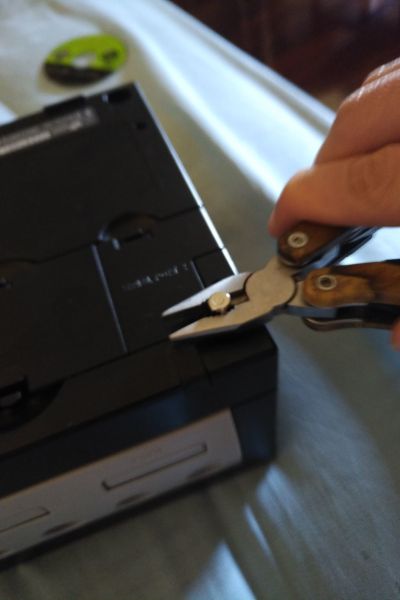
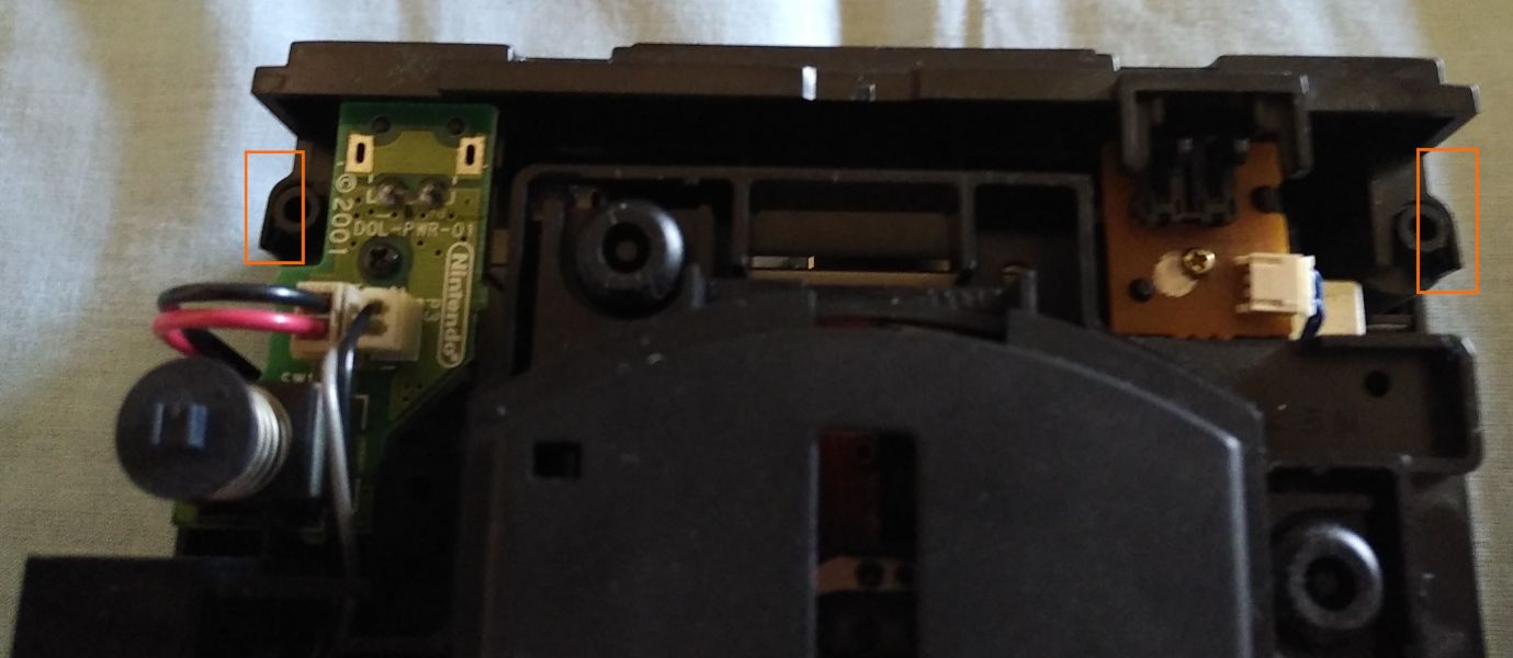
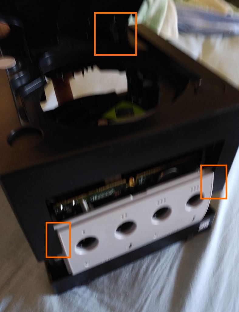
Remove the backplate (the frame around the video ports) by pushing towards the back, and slightly outward, the 2 tabs [highlighted in the picture] holding it .
The same procedure unclips the front panel. Pay attention to the flat cable that connects it to the mainboard.
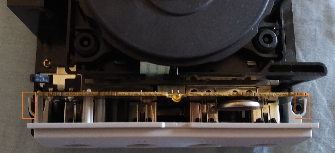
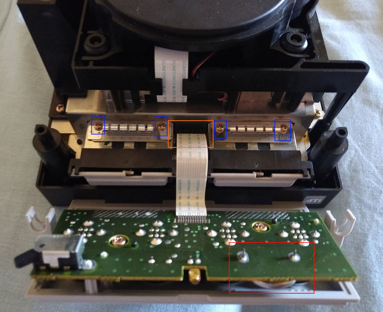
The cable [in orange] can be disconnected by pulling it straight up. Remove the pair of grounding springs, fixed by 2 screws [in blue] each.
While we're here, by removing 2 screws, we can separate the front panel from its PCB, to clean it up and/or to replace the clock and settings battery [in red].
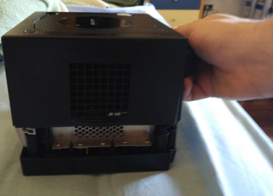
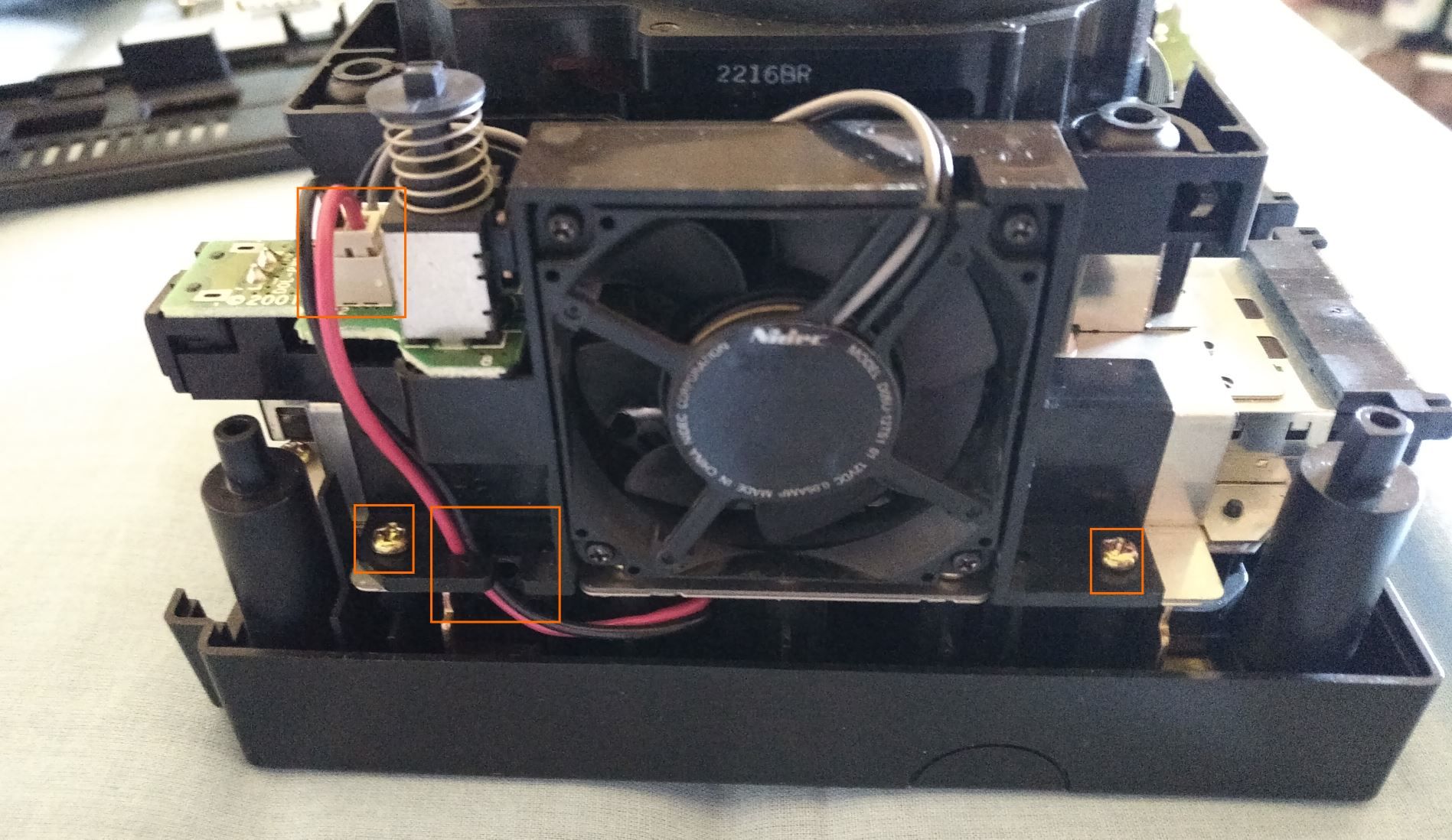
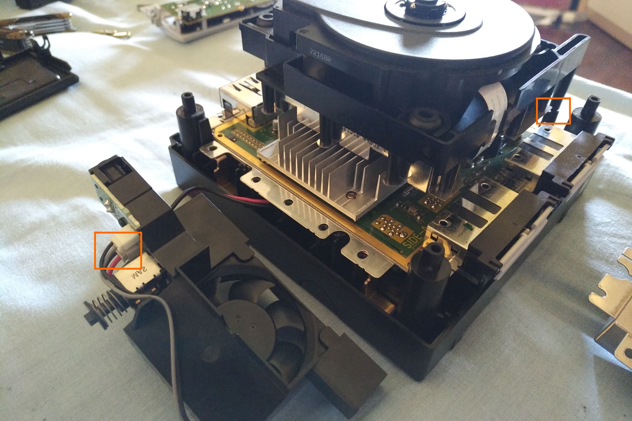
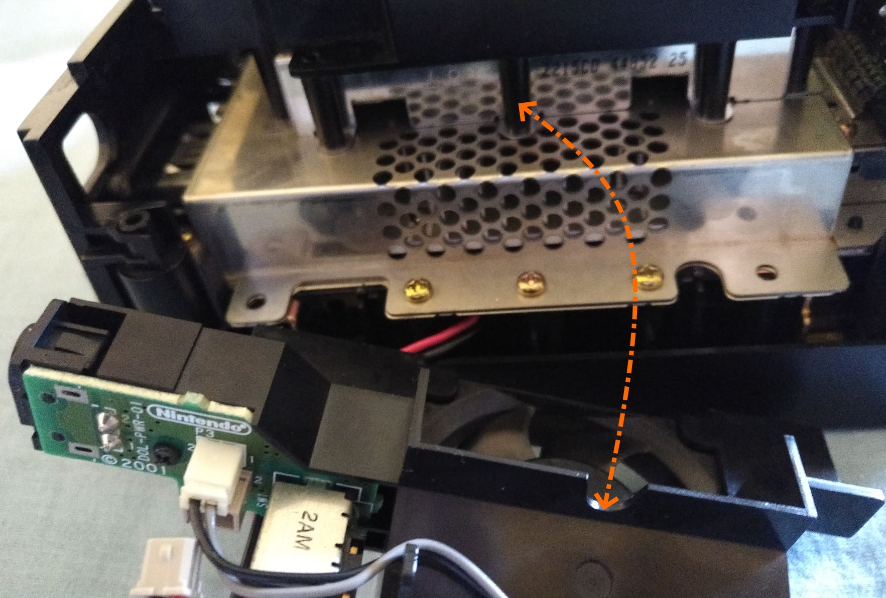
Let's look at the left side, where a black plastic frame holds together the power socket, switch, and fan.
Unplug the 2-pin cable that doesn't go to the fan, take it out of the notch on the bottom (one wire at a time), and remove the 2 screws holding the fan frame.
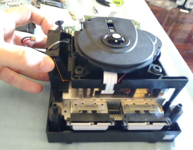
Remove the block by pulling it upwards and, by about 20°, away from the optical drive.
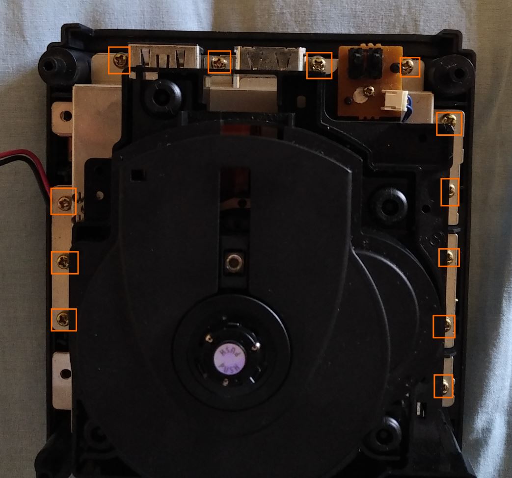
Remove the 12 remaining screws. It's not required (nor useful) to remove the smaller screw holding the lid switch.
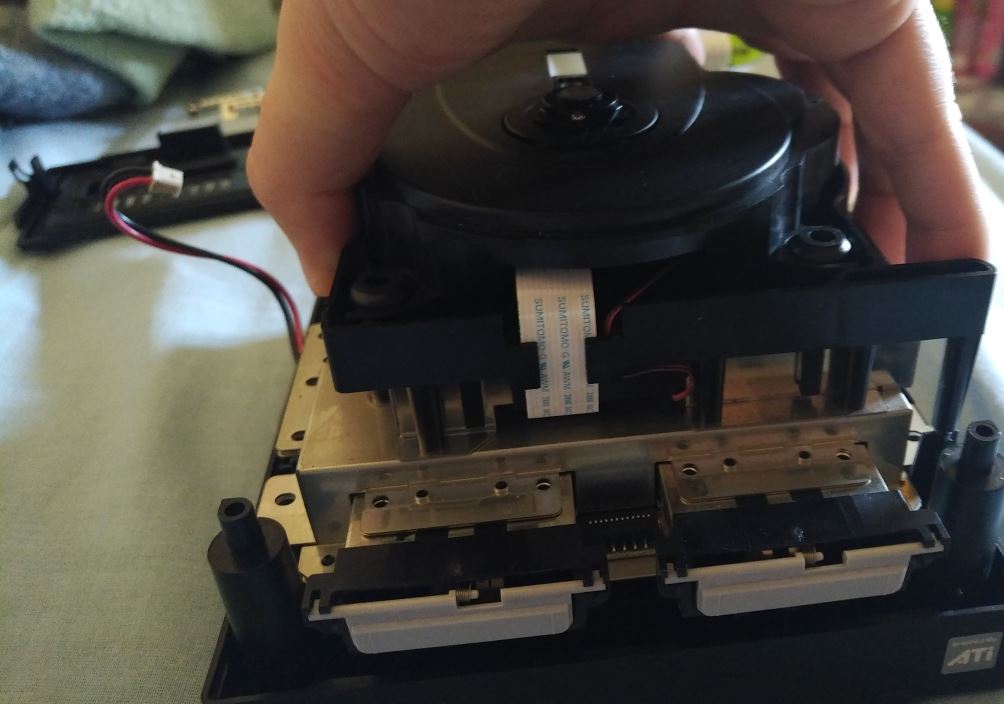
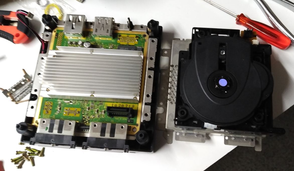
Grab the drive by the sides of the middle (rectangular) part, and pull it straight up for de-mating (get your mind out of the gutter). It's only connected at the corner where memory card slot B is.
If you wish to clean out the bottom unit, remove the 6 screws on the heatsink, and pull the motherboard up from the base (which on the DOL-001 contains the voltage regulators, to which it's connected in the rear left corner), otherwise skip this step.
I recommend against pulling the heatsink off the motherboard without good reason, you may break the thermal pads (which are 1,5 mm thick - not recommended to replace with thermal paste, even though with the limited powers instead you might get away with it)!
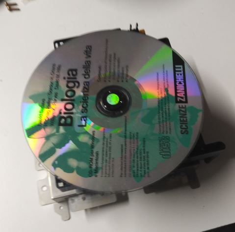
Next we'll be working on the bottom side of the disc unit. If you are going to work on a dirty and/or hard surface you may want to fit a disc to protect the lens - however, due to the protruding eject button, it's easy to have it fall off…
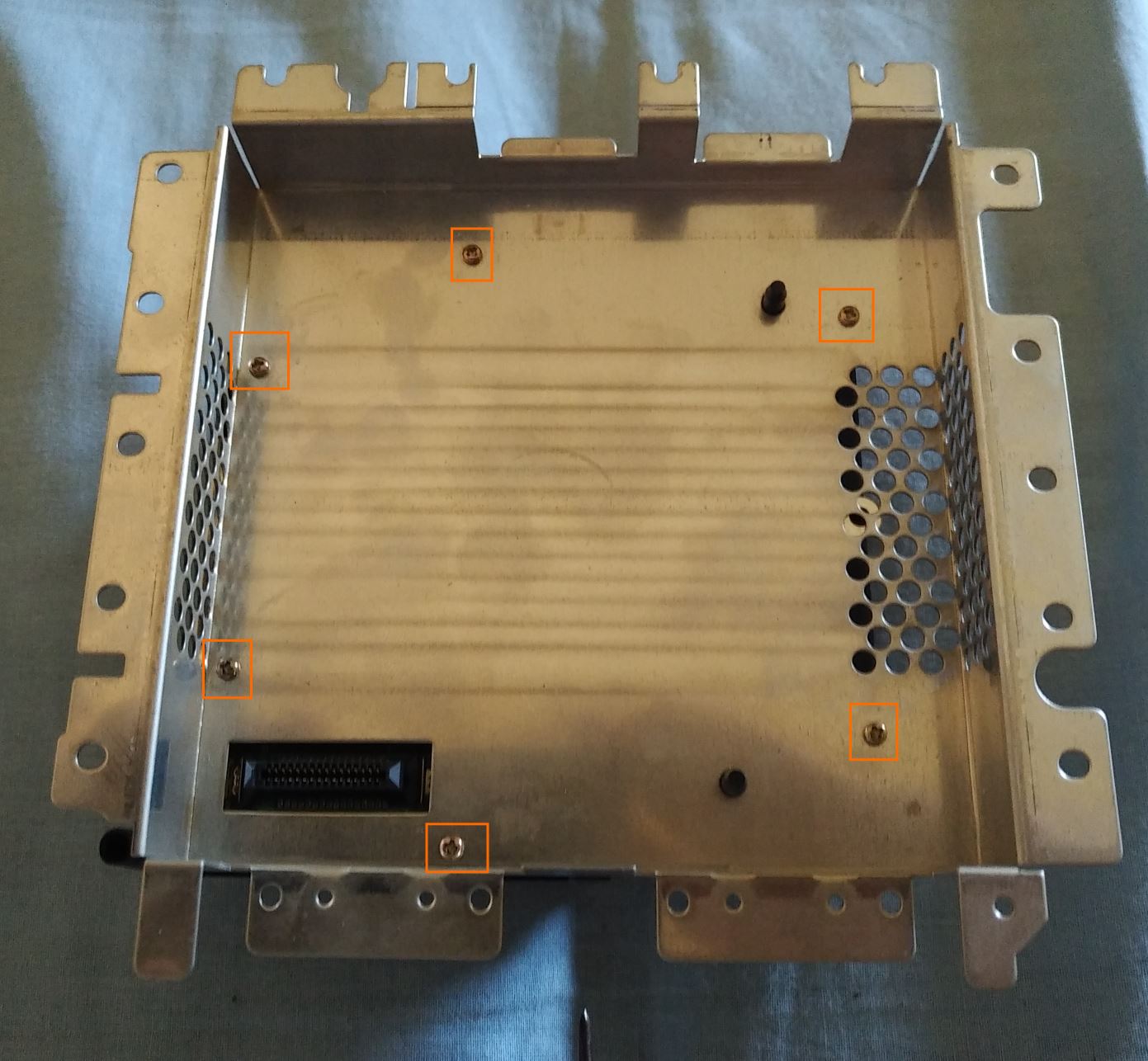
If working one-handed is an option (or if you have a significant other handy), a smarter option is to continue holding the unit as in step 7. Remove the six screws holding the shielding/base of the drive.
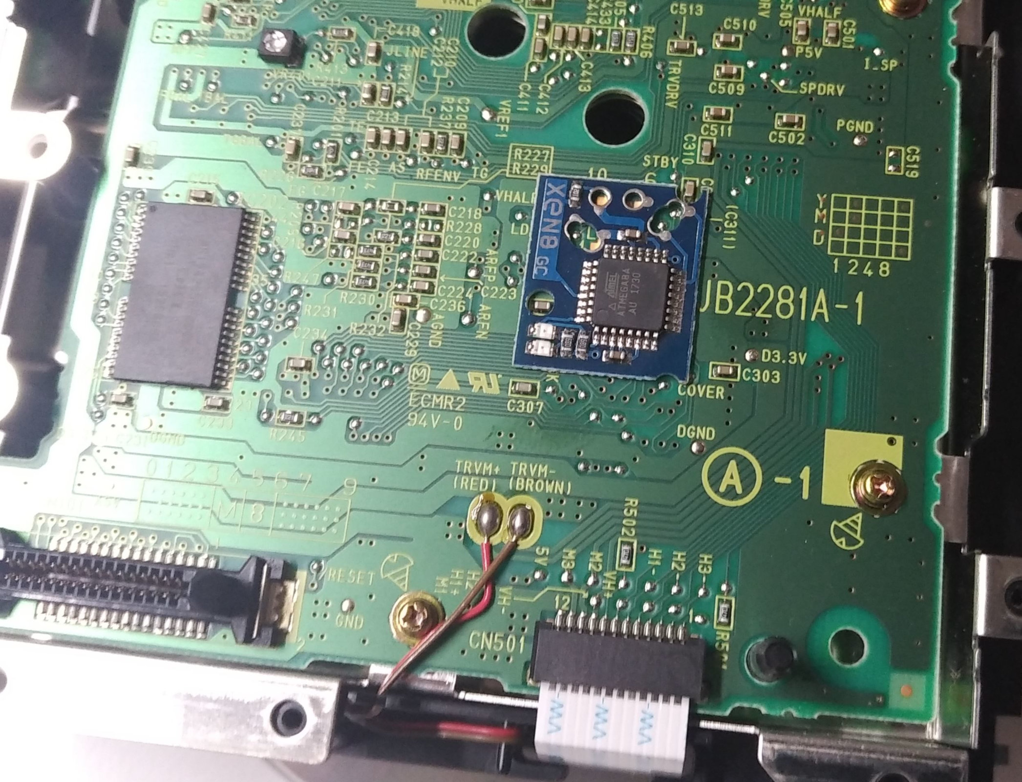
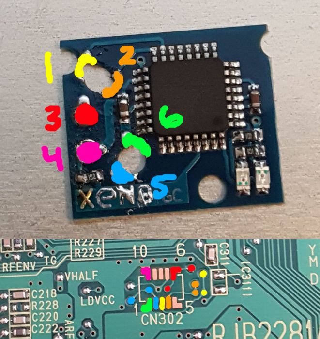
The XenoGC uses 4 data lines (plus 2 for power and ground).
All 6 of them are available on the lands for debug connector CN302 (not fitted on production consoles), as well as on alternate points on both sides of the PCB; we can proceed with a "quicksolder" setup, if compatible with your drive PCB (more professional and safer once mounted, but riskier to install and remove) or a more traditional setup with wires.
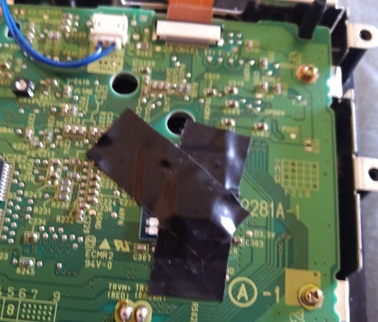
I suggest to cut a small rectangle of insulating tape, and cover the vias on the bottom side of the chip (without obstructing any holes).
I'm going to go with the quicksolder method, so after verifying which points are going to be actually used, I tinned the 3 affected pins of CN302, as well as the 3 other points, and again with the 6 (half-)holes on the chip. I then used tape to hold the half with the IC in place.
If you're going for a wired setup instead, here's a mirror of an image created by Madmorda of bitbuilt.net with some possible pinouts (even more available at the linked page).
Finally, protect the chip from the shielding with some more tape (but leave uncovered, at least initially, the pair of LEDs).
The console, out of the box, is optimized (for who knows what reason) only for the best performance with industrially pressed miniDVD-ROMs, on which the difference between an one and a zero is easier to see than on a DVD±R (which in turn are easier to read than ±RWs).
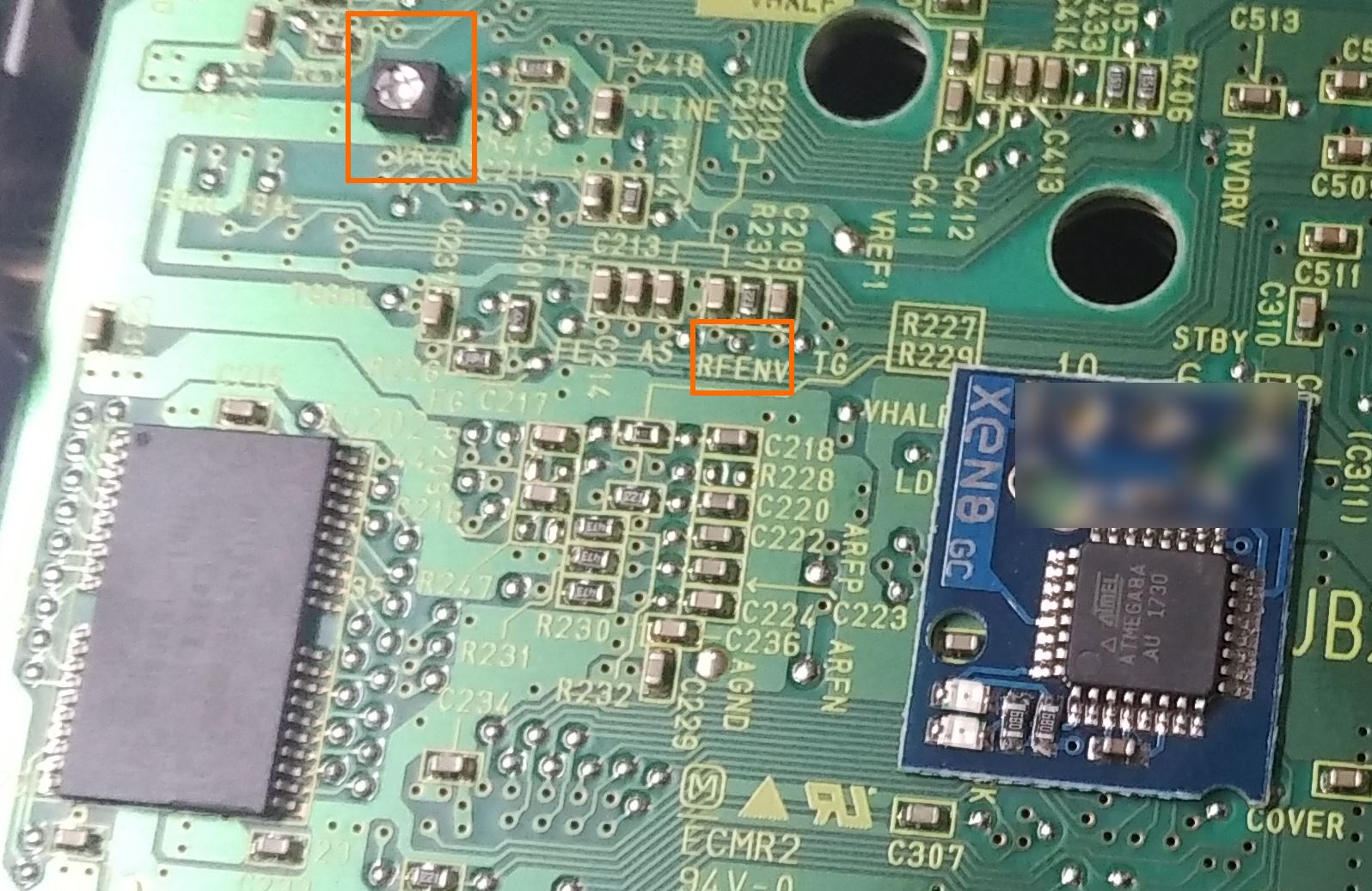
The scientifical method for adjusting a drive involves an oscilloscope capable of displaying the "eye pattern" and a professional grade test disc (or in this case where the individual disc(s) that are going to be used are a limited number and known, those discs).
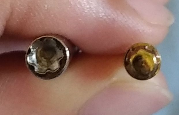
We can notice the (only) trimmer to adjust power, and the "RF envelope" point from which the eye pattern can be observed. Unlike certain other consoles, turning it all the way (minimum resistance) should not be destructive, since there's a fixed resistor in series - but blindly doing so is both stupid and not guaranteed to work!
Alternatively we can just plug the console back into power and a display, and adjust it via trial and error.
In either case we'll have to reconnect the drive (even without shielding), as well as the main 12 volt power line - and to remember to power off the console before pulling the drive again, plus remembering to push back both tabs of the lid switch!
You should also adjust in small steps (1/16 to 1/8 of a turn) - it's more sensitive than you think.
Speaking of the first boot after fitting the chip, observe the pair of LEDs to check for correct connections: the first one should light up immediately, blink once, turn off, then the 2nd one should come on and stay fixed. Current production clones make this check a bit harder, since both LEDs are red.
After unplugging the console again, simply invert the actions performed in steps 10 to 1. But keep in mind these notes:
Metal screw + plastic thread + ignorance of the trick = damage. After putting the screw against the thread (and moderately pushing against it), UNSCREW it until you hear a click (the screw aligning with the start of the thread), then be careful of the angle while tightening it.
In step 6, the screws must of course go in the correct holes, without occupying the two reserved for the fan.
In step 5, the notch in the fan frame has to end up resting against the middle "pole" of the optical drive.
In step 2, the folding disc cover must be open while reinstalling the top case, so it correctly engages the switch flaps; and of course, align it correctly with respect to the front and back plates!
Finally, remember to set the clock - even if the SRAM continues to run for over 30 minutes without a battery (unless you shorted to ground the leftmost pin of the front panel connector on the motherboard), the clock will likely have lost more than a few minutes…
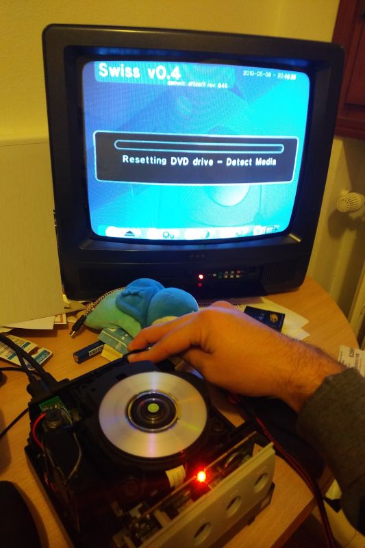
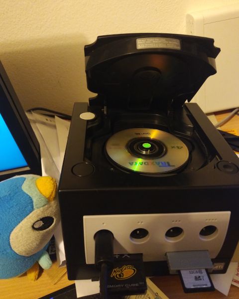
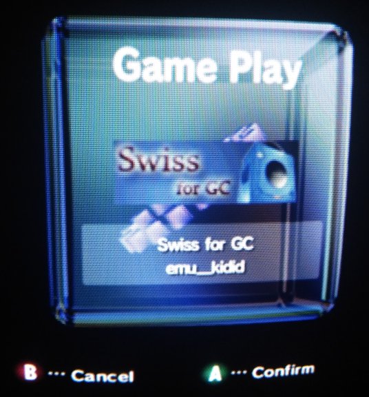
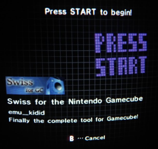
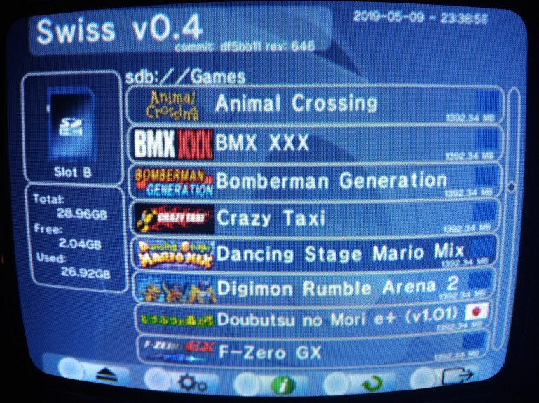
After getting your trusty, properly partitioned and formatted SD card, and placing some clean disc images (uncompressed, untrimmed, with GCM or ISO extension), music (MP3) or homebrews (in DOL format, or DOL+CLI) - insert the SD in the SD Gecko and that contraption into the console, start Swiss, and open the desired file!
Unsurprisingly, compatibility isn't 100% perfect - in case of doubt, it's always a smart idea to compare to other people's experiences.
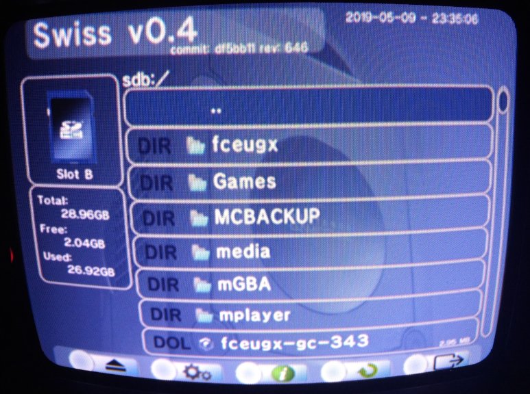
Press B to access the toolbar, the 5 options are respectively: device selection - Swiss settings - technical data about Swiss and your console - refresh - exit. I would suggest you to try the "alternate read patches" in the options - they offer generally faster loading for a tradeoff in compatibility.
Obviously, the DVD-R is not rewritable; when a new Swiss version (with appealing changes) is available, you can either burn a new disc, or have an updated version of Swiss autoloaded by itself as long as it's in the root of the SD and named boot.dol!
GL & HF!